
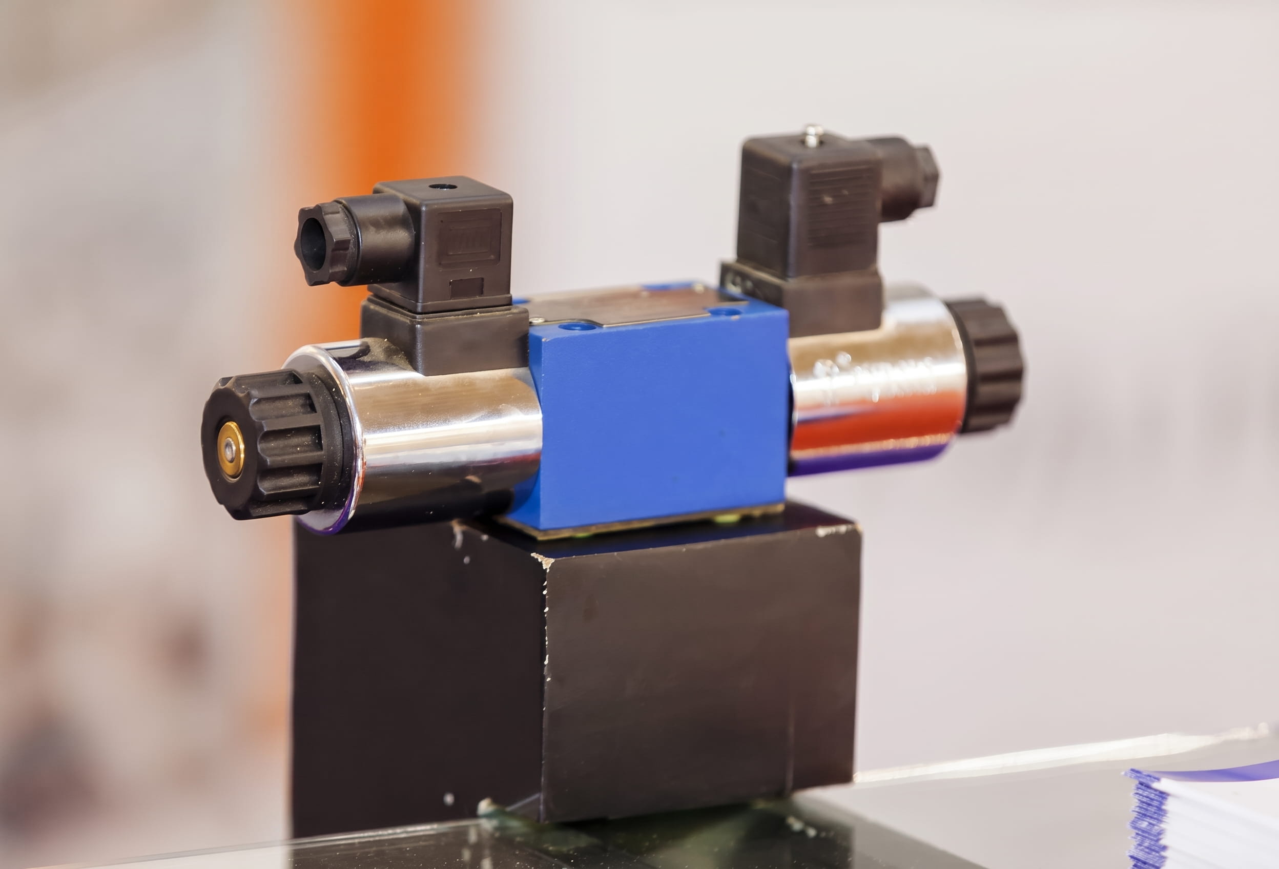
A requisition reading “NG6 directional valve, 24 V DC, ATEX” leaves several parts of the application unresolved. On a solvent-handling skid or in a combustible-dust area, for example, the valve has to match the site classification and temperature limit, as well as the hydraulic circuit, fluid and electrical installation. Under DSEAR, the employer classifies hazardous areas into zones, and the HSE also requires your overall explosion-safety measures to be verified by a competent person before a zoned workplace first comes into operation. Once that site information is available, you can test your Atos hydraulic valves requisition against six connected pass/fail checks.

Check 1: Certification and zone match
The required zone, gas or dust group and temperature classification need to appear in the selected certification. The Atos DHA technical table, for instance, includes Group II gas marking II 2G Ex db IIC and dust marking II 2D Ex tb IIIC, followed by the applicable temperature class or maximum surface temperature. The complete code matters because the DHA family also includes mining and North American variants.
Check 2: Protection concept and cable entry
Ex db is a flameproof enclosure designed to prevent an internal ignition from propagating outside; Ex tb uses protection by enclosure for dust. That protection extends through the electrical termination, and Atos provides specific GK-1/2, M20 × 1.5 or 1/2-inch NPT entry options. The assembly is completed with a separately ordered certified gland matched to the thread, cable construction and installation temperature.
Check 3: Surface and fluid temperatures
The DHA family spans several temperature markings and ambient ranges, so your selected solenoid code must be read as a complete line. Atos adds an important hydraulic condition: the fluid’s ignition temperature must be at least 50°C above the solenoid’s maximum surface temperature, so a 135°C surface limit calls for a fluid ignition temperature of at least 185°C.
Check 4: Ingress and ambient limits
IP66/67 applies to the solenoid enclosure when fitted with the relevant cable gland, defining the boundary for dust and water exposure, while the Ex marking defines the hazardous-atmosphere protection level. The general valve range is −20°C to +70°C, with /BT extending the lower limit to −40°C – the certification table then applies the ambient ceiling associated with the selected solenoid and temperature class. An outdoor skid expected to start at −25°C therefore needs /BT as part of its final code.
Check 5: Fluid and seal compatibility
Mineral oil may use NBR, FKM or HNBR. An HFDU/HFDR fluid moves the model code to FKM, while an HFC water-glycol system uses NBR or HNBR and brings the derated hydraulic limits in the next check into play. The exact fluid family and minimum and maximum temperatures therefore select the seal code together.
Check 6: Port pressures and flow
The size-06 DHA is rated up to 70 l/min, with 350 bar permitted at P, A and B and 210 bar at T. HFC operation reduces the maximum pressure to 210 bar and fluid temperature to 50°C. Recommended viscosity is 15–100 mm²/s, and the stated maximum contamination level is ISO 4406 20/18/15. The actual return pressure and fluid can therefore change a selection that appeared satisfactory from the headline rating.
Specifying Atos hydraulic valves with Hydrastar
To specify Atos hydraulic valves for a hazardous area, send us details of the Ex marking, ambient range, fluid and ignition temperature, supply voltage, gland arrangement, spool function, working flow and P/A/B/T pressures, and contact one of our engineers today. As an approved UK Atos valves distributor, we can then build the exact model code from our Atos Ex-proof range and check every hydraulic and environmental limit against your application.
Image Source: Envato