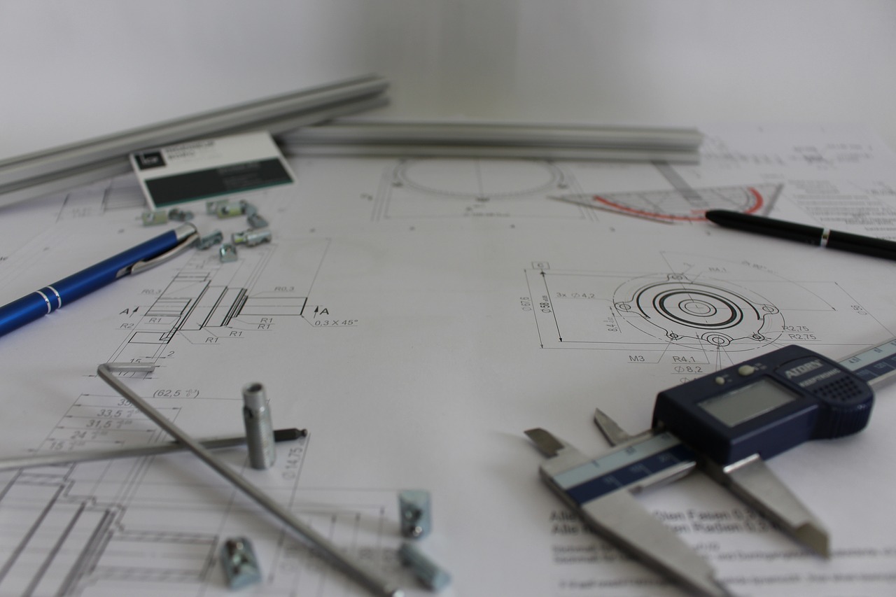
Every professionally-designed hydraulic system in use today started life as either a CAD digital or paper schematic – a technical drawing. A hydraulic technical drawing is a visual roadmap of the system layout, detailing hydraulic flow, inputs, outputs, and moving parts, alongside any motors or electromechanical components.
Each hydraulic line, reservoir, and mechanism is represented by a unique pictogram. A fixed set of symbols show engineers what should go where and how. Coloured lines represent the different types of motion, action, and power control you’d expect to find in a hydraulic mechanism.
But why are these complex diagrams created? Why are they so critical to the work of hydraulic engineers, operators, and technicians?
Quick, Efficient Inspections and Repairs
The main advantage of having a physical plan for your hydraulic system is that it makes troubleshooting, repairs, and modifications far smoother than having to map and plan out a new, circuit each time.
By comparing the current setup to the machine’s schematic, technicians can rapidly find any missing, broken, or malfunctioning items. Without a diagram, engineers may have to disassemble and analyse complex parts. Disassembly wastes time, money, and risks further issues from contamination and human error.
Machine owners can also create effective preventive maintenance plans using technical drawings. The hydraulic map highlights the areas of the hydraulic circuit most likely to degrade or fail.
Sharing Knowledge
All professional hydraulic schematics are drawn out using internationally recognised (ISO) symbols and criteria.
Since 1966, no written words have been allowed on hydraulic diagrams. All trained hydraulic engineers learn the language of lines, circles, and boxes to read and make technical drawings (much as with electrical circuits).
The hydraulic ISO standards allow hydraulic designers to avoid lengthy, wordy technical manuals and eliminate barriers in communication between companies and technicians speaking different languages.
Hydraulic symbolism also lets operators, technicians, and engineers performing modifications to mark changes and faults quickly, in a way easily understood by everyone else.
Insurance, Quality Control, and Professional Oversight
If a fault develops with the hydraulic system or an accident occurs due to misuse, the designer of the machine may be liable. Engineers need to have a reliable way of proving that their verified designs were designed and built to an excellent, safe standard.
Archived schematics help demonstrate that any faulty hydraulics were planned, revised, and tested to recognised criteria. With cross-referencing, technical drawings show where any unauthorised modifications, mixed installations, and changes were made to the system, invalidating the original guarantees.
Keeping hydraulic schematics to hand allows engineers to compare notes, sharing which designs and configurations work best for which application, and enabling precise cylinder and pump tuning.
Fluid Power Design Services From Hydrastar
Need assistance with custom hydraulic system design? At Hydrastar, our skilled hydraulic and pneumatic design engineers can transform any concept into detailed technical schematics. To discuss your ideas or find out more about our design service, give us a call today.
Image source: Pixabay


