The basic components of a pneumatic system are near universal, despite the wide variety of specifications available for individual units. A pneumatic system refers to any static installation that operates using a compressed gas – either air extracted from the environment or an inert gas. These are distinct from hydraulic systems, which use compressed fluid in liquid form, although the two installations may overlap in function.
Pneumatic systems are found in many industrial applications, engines and machines. The following basic components form part of every pneumatic system.
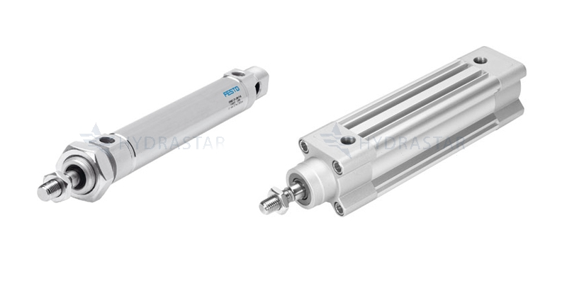
Actuator/Pneumatic Cylinder:
The actuator is a pneumatic motor that generates outward force through unequal pressure in a pneumatic cylinder, often connected to a piston rod mechanism. Pneumatic cylinders come in many types. Those that use piston rods are divided into single acting and double acting cylinders.
- A single acting pneumatic cylinder exerts a unidirectional outward force when the cylinder is pressurised. When the full outward stroke is reached, the compressed gas is expelled, creating a vacuum and allowing the piston rod to return to its start position.
- In a double acting cylinder, compressed gas is required for both outward and retract movements: the piston end is pressurised on the outward stroke and the rod end is pressurised on the return stroke. This has the advantage of increasing the stroke length and maintaining constant force on alternating movements.
So called ‘rodless cylinders’ do not use piston rods, but have an externally mounted carriage to carry out linear movements along a bearing. Also known as linear drives, rodless cylinders can be mechanically operated through compressed air, or magnetically powered.
Air Treatment System
Pneumatic cylinders are dependent on compressed air or inert gas, which enters the cylinder barrel at both ends via a control valve. Before the air reaches this valve it is channelled through a treatment system that composes the following parts:
Intake Filter
The intake filter channels either atmospheric air or an inert gas into the pneumatic system, filtering it of dust, VOCs and other unwanted particles. At this stage the air has a low pressure to volume ratio. This will change as it progresses through the treatment system.
Compressor
The compressor takes air and compresses it to reduce its volume and increase its temperature. There are several types of compressor, which operate under the principle of either positive displacement or dynamic displacement.
- Piston compressors – use a single acting or double acting piston to compress air and direct it through an outlet pipe into the cooler/separator/dryer unit.
- Diaphragm compressors – use a flexible rubber diaphragm in place of a piston to compress small quantities of air. These are used in sterile environments where contaminants from lubricating oil or piston surfaces may affect food, cosmetics or pharmaceuticals.
- Screw compressors – use a helical shaft to progressively compress air to high pressures. Useful when low to medium volumes of extremely compressed air are required. These compressors provide a continuous flow of compressed air, rather than the pulsating current characteristic of piston and diaphragm compressors.
Cooler, Separator & Dryer
Compression increases the temperature of the air, which must be cooled through a heat exchanger to reach operating temperature. Cooling units use a counter flow of air or water to extract and remove surplus heat from the compressed air.
The Separator, or drying unit, purges the compressed air of excess water vapour and gaseous contaminants. Dryers may use heat to drive off volatile components from the compressed gas, or chemical absorption (e.g. phosphoric pentoxide, calcium chloride or silicon dioxide). Some systems use refrigerant compressors to remove moisture from the compressed air.
The pure, dry compressed air is channelled into the receiver tank, sometimes after further filtration, while the moist, contaminated air is condensed to liquid form and expelled through a drain.
Receiver Tank
As pneumatic systems depend on a continuous supply of compressed air/gas, this fluid must be stored in a receiver tank. The large internal surface area of the receiver tank further helps to dissipate excess heat while maintaining the required pressure. This is measured by one or more pressure gauges. Compressed air is fed into the control valve by an exit pipe linked to a shut-off valve. As the pressure drops in the receiver tank the change is detected by pressure sensors at the inlet valve, which opens to refresh the tank.
Control Valve
The compressed gas as it enters the control valve to the actuator has a high pressure to volume ratio. The control valve, or regulator, feeds the gas into the actuator to control its speed and movements. Movement is achieved through motor displacement, so the purpose of the control valve is to moderate the flow rate and pump volume as the compressed air leaves the receiver tank. This is achieved through a series of stop valves, controlled by flow transducers, proximity sensors and pressure gauges.
How To Minimise Downtime With Pneumatic Plant & Machinery
Pneumatic plant depends on a complex interplay of compressed gas with a range of components. Failure at any stage of the system can affect the operational productivity of the whole, leading to reduced efficiency and downtime. To find out more about efficient design and maintenance for pneumatic systems, please download our free guide: How To Minimise Downtime With Pneumatic Plant & Machinery by clicking here.