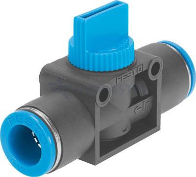
High-pressure hydraulic or pneumatic systems rely on multiple control valves to determine the loop’s flow direction, rate, and intensity. However, certain mechanical valves don’t remain static while in use; they can open, close, and variate their throughflow (via torque or piston motion).
Valve actuators, for example, trigger these changes on demand by rotating or lifting each valve’s internal block to alter the flow rate. Here’s how to choose the right actuator for your setup.
What Does A Valve Actuator Do?
A valve actuator interprets and converts an incoming signal (i.e. electrical jolt, fluid motion, kinetic motion, gas pressure) into a mechanical movement (e.g. pivoting a ball chamber via torque). These distinct units form part of each system’s direct control loop.
There are two valve actuator categories – mechanical and electromechanical. Both types of actuators have strengths and weaknesses that suit select applications, setups, and spaces over others. Your first step is to determine how closely each matches your machinery and your valve’s intended task.
1) Electromechanical actuators rely on sensor-triggered electric gear-and-ball motors to move attached valve internals back and forth.
- Actuators require constant power – not ideal for volatile, underwater, and remote places.
- Digital control capabilities – great for fixed installations that need remote access and precision settings.
- Excellent energy efficiency – c.90% reduction in power used per change, minimal flow interruption.
- Gradual reactions – grinding gear transfers switch valves in seconds, not microseconds.
- Motion profiling – different valve strokes, blocks, and turns can match individual actuator triggers to build complex ‘smart’ systems.
- Unobtrusive – electromechanical movement reduces spillage, ‘hissing’, and leakage. Nearby work is quieter, safer, and smoother.
2) Mechanical actuators use excess motion generated by in-line force (i.e. fluid, pneumatic flow rate) to trigger a level-activated ‘break’ shaft or lever.
- Fast release mechanisms – gear-free models trigger almost instantly.
- Fixed, a-to-b torque – with simple point-to-point motion, it can be harder to specify ‘axle’ mechanical actuators for diverse scenarios (e.g. varying pressure levels).
- Electricity free – no power required, ideal for isolated valves.
- Less efficient – manual actuators require more upkeep and servicing. They also waste more kinetic energy (per transfer) via impact resistance.
- Pressure activated – mechanical units can open or close valves on maximum fluid, gas, or manual pressure (i.e. lever release) without outside input.
- Safety first! – ideal for actuating valves for emergency stops, overflows, and escape pipelines.
Profiling And Sizing
Once you’ve narrowed down what type of actuator best fits your setup, measure it, and talk to your engineers and supplier about how it will fit into your system’s design. You’ll need to account for connector types and available space – actuators often add bulk to already tightly packed enclosures.
Both electromechanical and mechanical designs can fit onto valves horizontally and vertically. Switching to a linear valve that uses a ram instead of an axle is one easy way to reduce your actuator’s profile and footprint.
Stress Testing And Torque Calculation
Once you’ve narrowed down your design, you’ll need to run advanced calculations and field tests on how your actuator will perform in practice. Your may need to adjust the actuator’s torque force, positioning, and trigger intensity based on the results. Make sure to schedule regular maintenance and condition checks.
Valve Actuators, Hydraulics, And Neumatics From Hydrastar
Our team of experienced hydraulic and pneumatic design engineers can help you specify the right actuator valves for your application. To discuss your requirements, please call 01353 721 704 today.


