
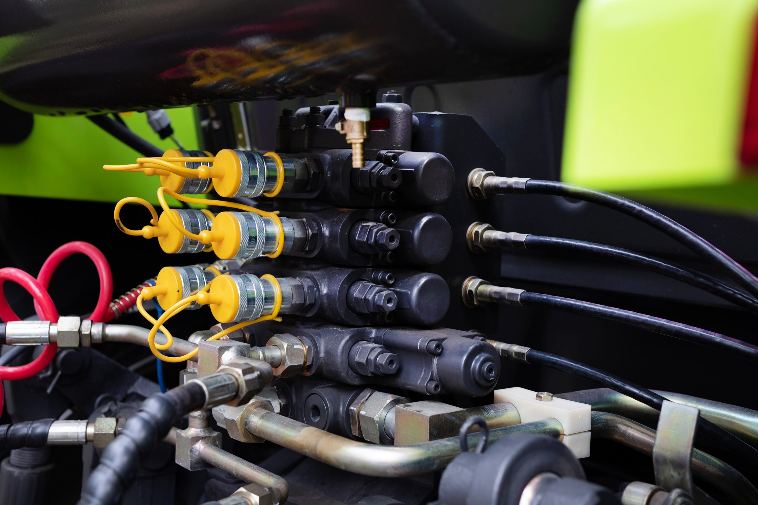
A hydraulic valve is often specified by thread, pressure rating and nominal bore; and while these details matter, they don’t automatically answer the harder circuit question: what should the valve allow your engineer to do once the system is built?

An inline valve, ball valve or diverter valve is not only a component in the flow path. Its position can also determine whether part of a hydraulic circuit can be isolated, whether residual pressure can be managed, whether a gauge or test point is protected, whether an actuator can be worked on without disturbing a wider assembly, and whether flow can be diverted without creating a confusing or unsafe operating state. Read on as we explore the place and function of isolation and flow control valves in a serviceable hydraulic circuit.
Valve Position Is A Circuit Design Decision
The same valve can be useful or awkward depending on where it sits. An isolation valve immediately upstream of a serviceable sub-assembly can allow a filter head, cooler, gauge branch, manifold section or actuator line to be worked on without draining more of the system than necessary. Placed in the wrong position, however, it may isolate the wrong volume, trap pressure in a dead leg, or leave the engineer unable to depressurise the section being opened.
The layout should be read in terms of contained volume. For example, when the valve closes, what fluid is trapped? Can that trapped volume expand with temperature? Is there a safe route to relieve it? Does the downstream side contain an actuator under load, a vertical cylinder, an accumulator, a pilot line or a flexible hose that could still move? These details decide whether the valve improves serviceability or simply moves the hazard to a less visible part of the circuit.
Isolation Needs A Pressure-Relief Route
A two-way ball valve can isolate flow effectively, but isolation alone is not the same as making a section safe to open. So if a valve closes around a section that can remain pressurised, the circuit needs a deliberate pressure-release path. That may be a bleed point, drain connection, test coupling, pressure gauge with suitable isolation, or a designed depressurisation route back to tank.
This is especially important where thermal expansion can raise pressure in a blocked-in section. A short length of hose, pipe or manifold passage filled with oil can experience pressure rise if the trapped oil heats up and has no relief path. The valve arrangement should therefore be reviewed with the operating and shutdown condition in mind, not only the running flow path.
Calculating Flow Loss
Every inline valve introduces a pressure drop. The size of that drop depends on internal geometry, port size, flow rate, oil viscosity, fitting transitions and whether the valve is full-bore or reduced-bore. In high-flow sections, even a modest restriction can create heat and reduce available pressure downstream.
The useful engineering check is power loss:
P_loss(kW) = Δp(bar) × Q(L/min) ÷ 600
This equation turns a pressure-drop concern into something operationally useful – e.g. a valve causing 5 bar loss at 120 L/min is dissipating about 1 kW as heat. In a low-duty maintenance branch, that may be irrelevant, but in a continuously flowing pressure line or cooler bypass, it may change the thermal behaviour of the system.
This is why your valve location is important. A valve in an occasional service leg can be selected differently from one in a main pressure line, return header or continuously circulating loop.
Diverter Valves Need Unambiguous States
A diverter valve should make the intended flow path obvious. Two-position and three-position valves can create different behaviours depending on whether the ports are arranged as L-port, T-port, blocked-centre, common-inlet or common-outlet configurations. If the wrong pattern is selected, the valve may connect circuits that should remain separate, block a return path, starve one function, or leave an actuator in an unexpected condition during changeover.
The handle position, port marking and installed orientation need the same attention as the hydraulic rating. A diverter valve hidden in a crowded panel or installed with unclear port identification can become a maintenance problem even if it is technically correct. Where the valve selects between two services, the circuit should also make clear whether both services can ever be connected, whether one must always remain open, and what happens during transition between positions.
Protect Gauges And Test Points Without Hiding The Reading
Isolation valves are often used around pressure gauges, test points and diagnostic branches. That can protect instrumentation from continuous pressure pulses, allow gauges to be changed, or keep a test connection clean until it is needed.
The risk is that an isolated gauge can give the wrong impression if the valve position is not obvious. A gauge may hold a trapped reading after isolation, or show no pressure because its branch is closed while the main line remains live. If gauge isolation is used, the layout should make the valve status clear and include a suitable method for venting the gauge side before removal. For test points, the same principle applies. The connection should sit where the reading is meaningful, not simply where access is convenient. A test point upstream of a valve, downstream of a valve, or across a restriction can answer different questions.
Find Out More
For support with inline valve, ball valves, diverter valves or hydraulic fittings, please [speak to Hydrastar] about the right products for your circuit requirements.
Image Source: Envato